Creating Part Templates
Tessonics Corporation has made every effort to ensure the accuracy and completeness of this document; however, because ongoing efforts are made to continually improve the capabilities of our products, we cannot guarantee the accuracy of the contents of this document. We disclaim liability for errors, omissions, or future changes herein.
Tessonics Corporation and its subsidiaries reserve the right to make changes, corrections, enhancements, modifications and improvements to its products and/or to this document at any time without notice.
Information in this document supersedes and replaces information previously supplied in any prior versions of this document.
Tessonics and the Tessonics logo are trademarks of Tessonics Corporation.
All other trademarks mentioned herein are the property of their respective owners.
©2007–2024 Tessonics Corporation. All rights reserved.
No part of this document may be copied, reproduced, or translated, without the prior written consent of Tessonics Corporation.
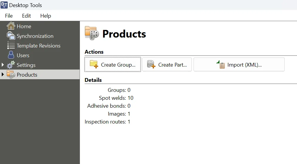
Part templates are stored in the Products catalog. Click on Products on the left-hand menu to bring up the products page.
 {min-width=45%}
Groups
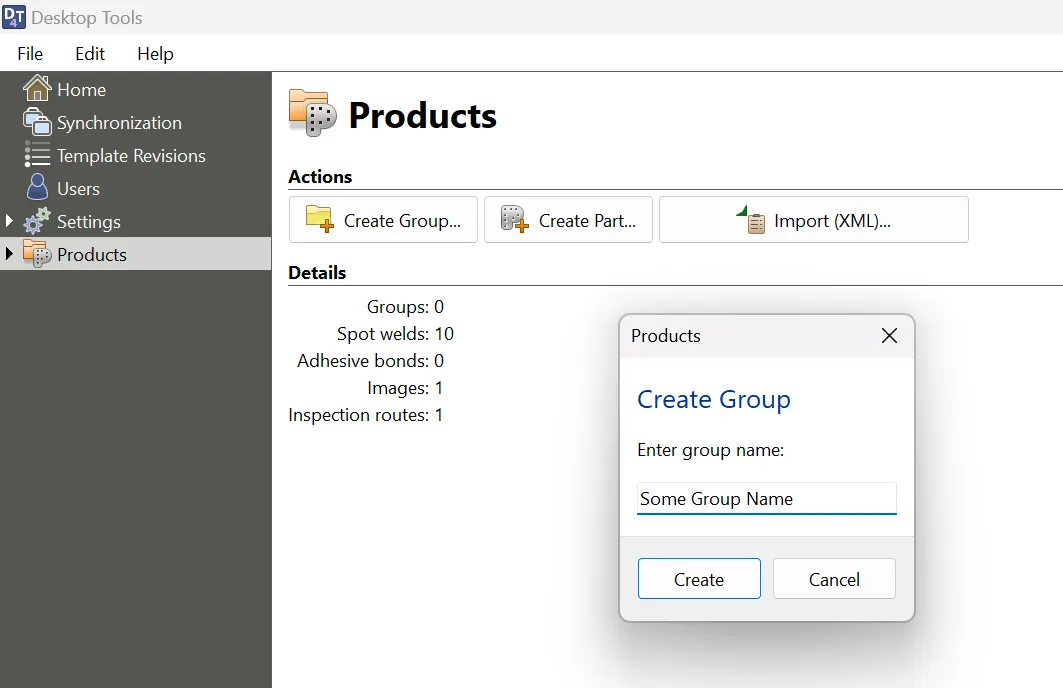
Parts can be organized into groups. To add a new group to the top level of the products catalog, click Create Group on the products page.
 {min-width=45%}
Groups can also be nested within other groups. To create a child subgroup within an already-created parent group, you can do one of two things:
- Click on the group in question, then on the main window, click Create Subgroup.
- Click on name of the parent group in the left-hand menu, and click Create Group.
Parts
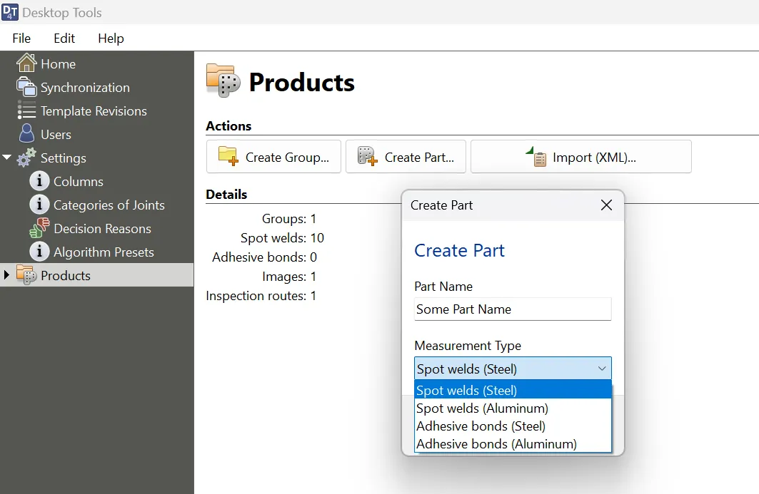
Parts can either be created within groups, or within the top level of the products catalog. To create a part, click on the group that you want to add it to (or alternatively, navigate to the products page) and click Create Part.
You will be prompted to enter a part name, and to select a measurement type for the part. The following measurement types are supported:
- Welds (steel)
- Welds (aluminum)
- Adhesive bonds (steel)
- Adhesive bonds (aluminum)
Part names must be unique within the group that they belong to.
 {min-width=45%}
Adding Measurement Locations
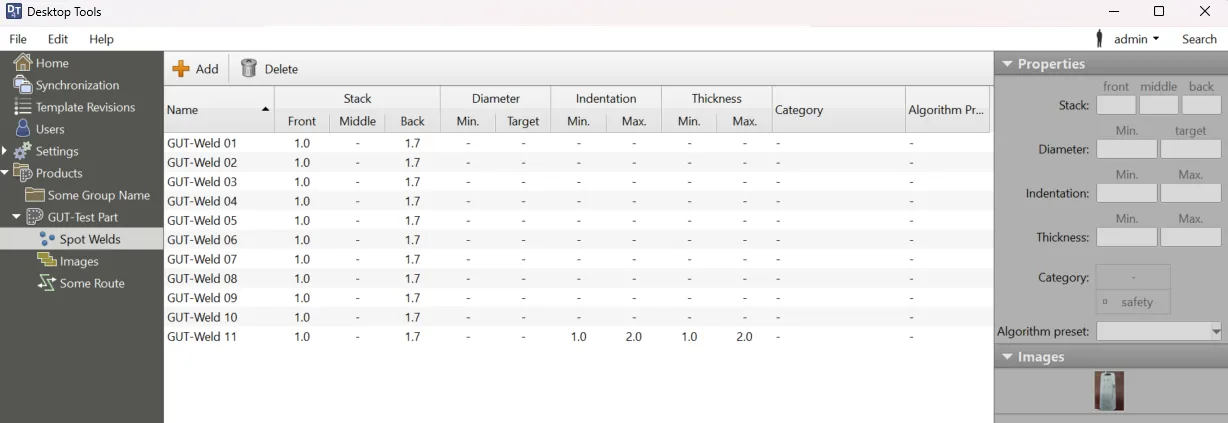
Click the Add button to add measurements. You can either add a single measurement, many measurements at once, or copy data from the clipboard on your PC. Once you’ve added your measurements to the grid, you can edit their properties. Click on a measurement to highlight it, and then either edit the property value directly on the grid, or use the controls on the right side of the page under “Properties”. The following properties are editable:
For Welds:
- Stack Front
- Stack Middle
- Stack Back
- Diameter Min.
- Diameter Target
- Indentation Min.
- Indentation Max.
- Thickness Min.
- Thickness Max.
- Category
- Robot Name
- Robot Schedule
For Bonds:
- Slots
- Width
- Category
- Stack Front
- Stack Back
- Robot Name
- Robot Schedule
Import Measurements from the Clipboard
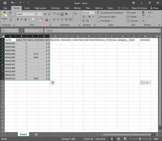
The desktop tools software allows for the bulk-adding of measurements from the Windows clipboard. This allows you to copy and paste data from a Microsoft Excel spreadsheet to quickly import it into your database. First, open your spreadsheet in Excel, and select the data you wish to import into the database. The right click and select Copy.
 {min-width=45%}
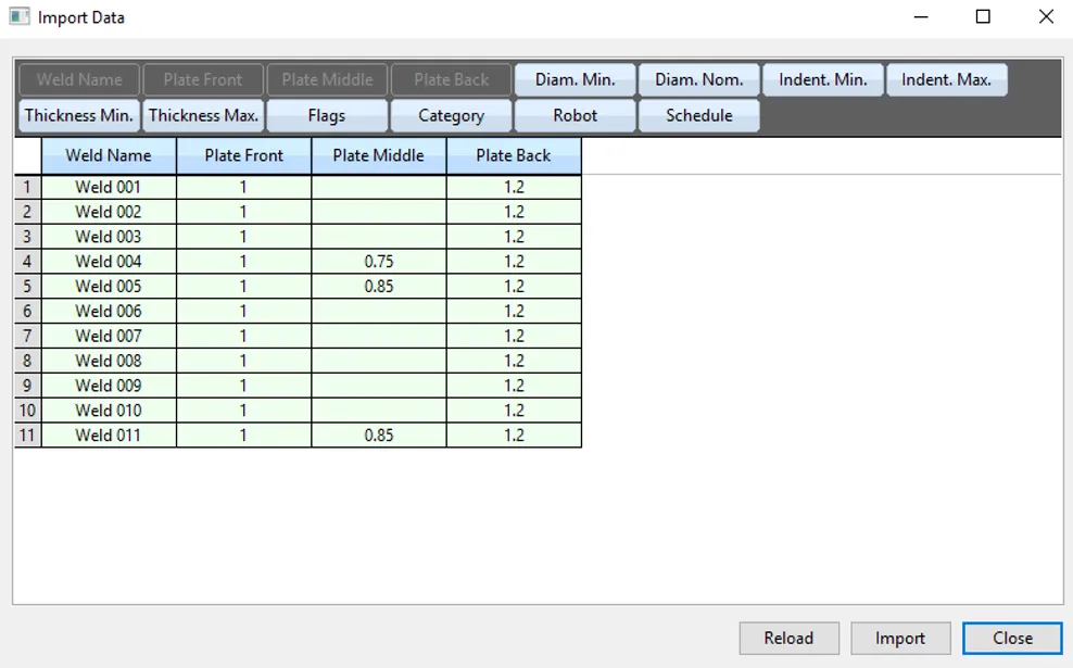
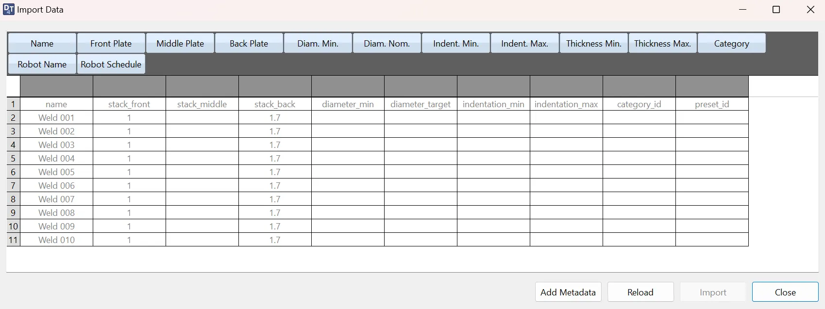
In the desktop tools, right click on the measurement grid, and select Import from Clipboard. Drag the column headers at the top of the window that appears over the data that matches the column from your spreadsheet.
Once done, click Import, and the data will appear in the grid.
 {min-width=45%}
 {min-width=45%}
Similarly, you can export to the clipboard from Desktop Tools, and paste the data into an Excel spreadsheet. You can do this by selecting the rows you wish to copy, right-click and select Export to Clipboard.
!Note: Just like in other programs, you can use the Ctrl key while selecting to select multiple rows, and the Shift key while selecting to select the range between two rows.
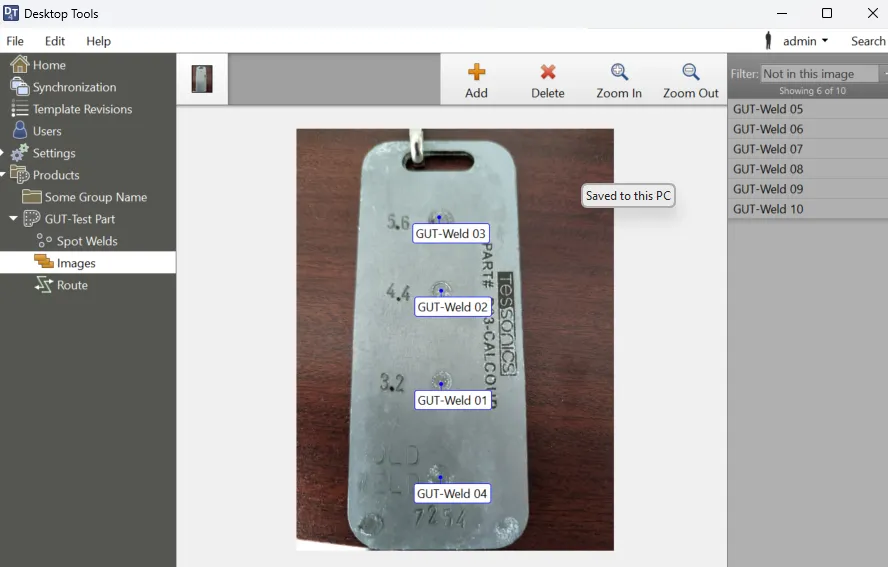
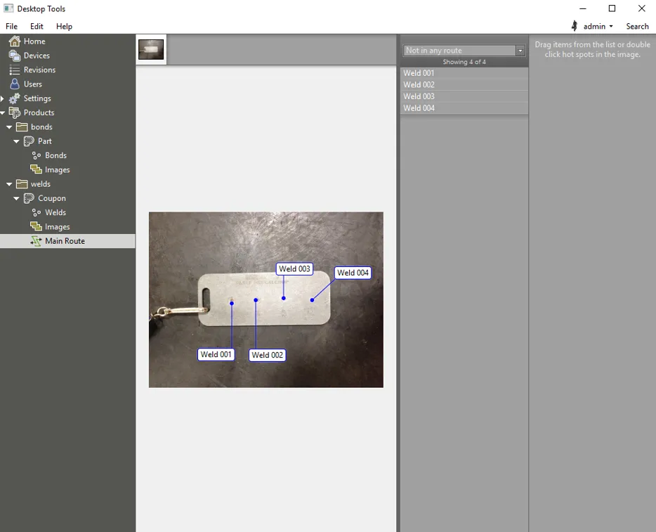
Adding Part Images
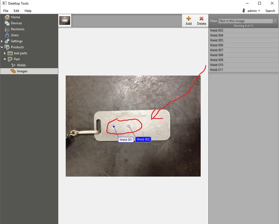
Once you have your location data defined, the next step is to add images of your parts to the database. Click on the images tab to get started.
Click Add to include an image in your part. You will be provided with a Windows Explorer window to make your selection. Once the image has been added, you can drag locations from the right side of the window onto your image. This represents the locations of different welds on the image.
 {min-width=45%}
 {min-width=45%}
Note the filer at the top right. This will filter which welds show up in the right menu to clean up the display. Possible values are:
- Show all items
- Only in this image
- Not in this image
- Not in any of the images
You can add as many images as you want to the part. Once you’ve completed adding your images and dragging the locations onto them, the next step is to set up routes.
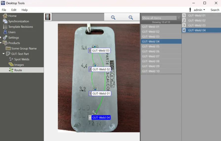
Adding Inspection Routes
When inspecting a specific part on the RSWA, you need to provide a route for the inspector the follow. A route is effectively the path you took when inspecting the welds.
To create a new route, select the part from the Products catalog and click Create Route. You will then be prompted to provide a route name, and then be taken to the route editor page.
 {min-width=45%}
 {min-width=45%}
To add a location to the route, either double click on the label on the image, or drag the location from the location list (middle gray menu) to the route list.
- Locations can be re-ordered in the route by dragging them in the list.
- Routes can also span multiple images.
When you add a new route, it appears in the products catalog under the part which it belongs to. You can add as many routes to a part as you want, and welds can belong to many routes.