Main Window and Terminology
Tessonics Corporation has made every effort to ensure the accuracy and completeness of this document; however, because ongoing efforts are made to continually improve the capabilities of our products, we cannot guarantee the accuracy of the contents of this document. We disclaim liability for errors, omissions, or future changes herein.
Tessonics Corporation and its subsidiaries reserve the right to make changes, corrections, enhancements, modifications and improvements to its products and/or to this document at any time without notice.
Information in this document supersedes and replaces information previously supplied in any prior versions of this document.
Tessonics and the Tessonics logo are trademarks of Tessonics Corporation.
All other trademarks mentioned herein are the property of their respective owners.
©2007–2024 Tessonics Corporation. All rights reserved.
No part of this document may be copied, reproduced, or translated, without the prior written consent of Tessonics Corporation.
The Main window consists of seven areas, which are explained in the following sections:
 {min-width=60%}
Terminology used in this chapter:
- Inspection
- A group of weld measurements that are saved together.
- Part
- A manufactured object that has spot-welds.
- Inspection Order
- The order in which spot-welds on a Part are to be measured.
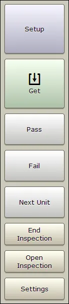
Button Area
 {options=right height=35%}
- Setup
- Setup the unit for measuring welds on a specific metal stack.
- Get
- Takes a single measurement. (Push and hold to enter continuous mode; see Continuous Mode Panel.)
The next three buttons are used with inspections. See the Inspections section for more details.
- Pass
- Clicking this button passes the current weld in the weld list. If a measurement hasn’t been performed or the pass button is held down, a pop-up list of reasons for passing the weld will appear.
- Fail
- Clicking this button fails the current weld in the weld list. You must select a reason for failing a weld from the pop-up list that appears.
- Next Unit (In Part Inspection mode)
- Shown only for Part Inspections, this button replaces the New Weld button. Pressing it will start a new inspection using the same part you were working on.
- New Weld (In Custom Inspection mode)
- Shown only for a Custom Inspection, this button adds a weld to the list of measured welds.
The next two buttons allow starting, saving, and opening inspections. See the Inspections section for more details.
- New Inspection/End Inspection
- Starts new inspection. Once an inspection is started, this button changes to End Inspection.
- Open Inspection
- Opens a previously stored inspection (see Opening Inspections).
- Settings
- Allows changing various application settings (see Settings).
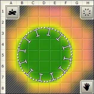
C-Scan Area
This area shows the image that is created from the collected measurement data. The green areas have fusion and the red areas do not have fusion.
 {min-width=50%}
- Dotted Circle
- Shows the automatic estimation of weld nugget location and diameter. If the estimation is off it can be manually adjusted by clicking the hand icon. Dragging the edge of the circle will resize it and dragging the interior of the circle will reposition it. The dots turn blue when in manual mode. Clicking the hand a second time will undo any manual modifications.
- Small Background Squares
- Represent the transducer’s elements. The currently selected elements waveform will be shown in A-scan area (see A-Scan Area).
- Spinning Wheel
- Shows minimum/nominal size of the weld.
- Indentation Button
- Sets acceptable indentation range for the weld being measured.
- Hand Button
- Switches to manual circle sizing and back.
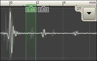
A-Scan Area
The A-Scan area shows waveforms (A-Scans) for the individual elements in the transducer’s matrix.
 {min-width=50%}
You can choose which one out of the 52 matrix elements is displayed by making a selection in the C-scan area (see C-Scan Area).
- White Curve
- Shows the A-scan for the currently selected element.
- Shadow in Background
- Shows the composed A-scans from all the elements.
- Number Boxes
- Position of front-wall and back-wall reflections.
- Green Vertical Lines
- Gates showing the range for C-scan acquisition. These gates are set automatically when you press the Setup button. To adjust them manually, push and hold the touch screen inside the A-scan area.
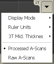
Additional options are available through a drop down menu:
 {height=35%}
- Display Mode
- Used to change how a-scans are displayed. The default value is Bipolar.
- Ruler Units
- Used to change the units used for the a-scan ruler. The default is Depth.
- 3T Mid. Thickness
- Used to set the thickness of the middle plate when performing 3T inspections. Make sure this to off when performing a 2T inspection.
- Processed A-Scans
- Use this option to see a-scans with signal processing (default)
- Raw A-Scans
- Use this option to see a-scans without signal processing.
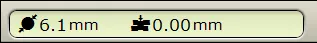
Indicator Area
 {width=80%}
The indicator area shows the estimations for the current weld nugget size and indentation. This area will also indicate errors involving the ultrasonic hardware. shows errors involving the ultrasonic hardware.
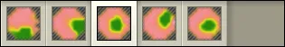
Measurement History Area
 {width=80%}
This bar contains a history of all the measurements taken, stored in chronological order from the left. If you are not in an inspection it simply shows the history of the measurements taken. If you are in an inspection this bar contains all the measurements for a specific box in the Inspection Data section. Clicking on a measurement in the history bar will reload the measurement so it can be re-examined, and also change the measurement that is shown in the Inspection.
Status Bar
 {width=80%}
Shows the currently logged in user, Inspection and Inspection Order that is being worked on.
Settings
This section discusses various settings of the Array Explorer application. Access to some settings is restricted depending on your permission level.
To access settings, click the Settings button in the button area.
Continuous Mode Panel
This setting determines the number of measurements taken in continuous mode. It can be set to take between 5 and 100 measurements (determines how long continuous mode lasts for).
To enter continuous mode, push and hold the Get button. To leave continuous mode, click the Get button again, or simply wait until RSWA cycles through the specified number of measurements.
Algorithm Panel
Algorithm panel is available only to users with the Advanced access level.
- Absolute adjustment
- A constant value, between -2.0 mm and 2.0 mm, that is added to the diameter of every measurement.
- Minimum size adjustment
- When activated, this option will fit auto sized circles tight around the green area on C-scan. Tessonics recommends to activate this option.
- Secondary Echo Processing
- Activates the Secondary Echo Processing algorithm.
When metal plates have partial fusion, for example through a coating layer, the first internal reflection is often very small and hard to detect. However, these small amplitudes accumulate in the subsequent passes of sound through the stack:
 {min-width=40%}
The amplitudes of reflections in this case are shown below:
 {min-width=50%}
Then the Secondary Echo mode is activated, the presence of the secondary echoes is detected. There are three levels of the sensitivity: Subtle, Moderate, and Full. In the full mode, the sensitivity of the algorithm is very strong, so that even small reflections are detected. In the subtle mode the algorithm is least sensitive, the secondary echo signal must be relatively strong to get detected. We recommend using Moderate mode when inspecting steel and Subtle mode for inspecting aluminum. Also we recommend to use Aggressive Peak Detector mode (See below) when the secondary echo mode is activated.
- Peak Detector
- Controls signal peak detection. The Standard mode corresponds to the peak detection algorithm used in the previous versions of the Array Explorer. The Aggressive mode is designed to improve stick weld detection as well as detection of welds with curved surfaces. Then the Aggressive mode is activated, the entire wave form is analyzed. The amplitude of reflection within the signal gates is compared to both the back-wall reflection and to the front surface reflection. Other factors, such as the distance to the front surface reflection are also taken into account. The new Smart option further improves the aggressive mode to provide more stable readings on curved surfaces.
- Echo Shape Processing
- When activated, enables an additional step in the signal processing algorithm that provides better detection for stick welds.
- Surface Follower
- Controls how gates are positioned relative to the surface. When None is selected, the signal detection gates keep the same level regardless of surface topology (see image on the left). When 100% is selected, the signal detection gates follow the surface profile (see image on the right). Settings of 25%, 50%, and 75% allow for intermediate gate positioning.
 {min-width=50%}
Hardware Panel
Hardware panel is available only to users with the Advanced access level.
- Disable controller
- Allows to disable controller activation
Waveform Panel
Waveform panel is available only to users with the Admin access level.
- Supersampling
- The base sampling frequency is 66.6 MHz; supersampling is a multiplier that allows you to increase the sampling frequency (i.e. if supersampling is set to three the sampling frequency is tripled).
- Averaging
- This is a signal processing technique that reduces the amount of noise; multiple scans are taken and the average over the scans is used.
- Inter-pass delay
- Allows you to change the time delay between averaging scans.
Adjust Signal
Adjust Signal panel is available only to users with the Adjust Signal permission.
To aid in setting these parameters a grid of transducer elements and an A-scan window is shown. Clicking on a transducer element will cause the signal from that element to populate the A-scan window.
- Delay
- Controls the data acquisition delay. Then you change this parameter, the entire A-scan curve is shifted in the A-scan window. A properly calibrated tool must show the front surface reflection within the gates (green area in A-scan window).
- Gain
- Controls the amplitude of the signal. The signal should be adjusted so that the peaks are close to the horizontal lines connecting the gates (green area in A-scan window). For this adjustment, the transducer must be placed on a thick metal plate.
- Auto Setup
- Use Auto Setup to automatically initialize the Delay and Gain parameters
User Interface
These settings allow you to configure various user interface options.
C-Scan Area settings:
- Display type
- Allows you to choose between a smoothed color image and a gray-scale block image.
- In-air indicator
- Allows you to choose if you want to be warned when the transducer is not coupled to a sample and a measurement is taken.
- Setup warnings
- Warns the user if:
- Setup button wasn’t pressed before the Get button on a weld that has no recorded front plate thickness
- Setup button acquires a front plate thickness that doesn’t match the recorded front plate thickness (possibly checking the wrong weld)
The level of warning can be adjusted from none (Hide), to many warnings (Many). They correspond to how close the measured front plate thickness has to be to the recorded front plate thickness.
Note
The Setup Warnings are only meant to help inspectors. They should not be relied upon.- Automatic decision
- Controls the automatic decision mode. When automatic decision mode is activated, the obtained diamater and indentation are compared to the specified ranges (minimum nugget, minimum and maximum indentations) via the following procedure:
The obtained diameter is compared against the minimum nugget diameter. If the obtained diameter is too small, then the decision algorithm determines that the weld is bad.
If the obtained diameter is greater than the minimum nugget diameter and is also less than the target nugget diameter, then the decision algorithm determines that the weld is marginal. If the obtained diameter is greater than or equal to the target diameter, then the algorithm determines that the weld is good.
Once a decision has been made based on the nugget diameter, the algorithm then checks the obtained indentation against the minimum and maximum indentation settings. If the obtained indentation is too small or too large, then the algorithm determines that the weld is bad, regardless of the decision it made based on the nugget diameter. If the indentation is within the minimum and maximum settings, then the previous decision made based on the nugget diameter is kept.
The automatic decision mode is only available when you run the software as Admin. The possible settings are:
- Hide – do not show automatic decisions (default)
- Show – show a quality decision suggestion, it is still up to the operator to make a final decision by pressing Pass or Fail buttons
- Show and Apply – makes an automatic decision and automatically passes or fails the weld
Note
In order to use automatic decisions, you must specify a nugget diameter for the weld.- Minimum diameter
- This setting is only available when you run the software as Admin. In addition to the standard diameter reading, the software will also estimate a minimum diameter of the nugget. The minimum diameter reading is trying to stay more on the safe side of the diameter estimation. In the case of oval nuggets shapes, the estimated value will be closer to the minimum size of the nugget. In the example below, the standard diameter reading would be around (5.0 + 6.6) / 2 = 5.8mm and the minimum size would be 5.0mm.
 {min-width=50%}
Other settings:
- Second interface
- Controls the second interface indicator. When Position is chosen, the A-scan window shows the absolute position of the second interface. When Thickness is chosen, it shows the thickness of the stack measured through the center of the nugget.
- Indentation indicator
- Controls how the indentation is shown in the Indicator area (Indicator Area). When the Depth option is chosen the indentation is shown in millimeters. When Percent option is chosen, the indentation is shown as percentage (relative to the front plate thickness).
- Use coin element G for AutoSetup
- This option changes the message that is displayed during Auto Setup procedure. When set to ‘No’, a standard message is displayed that recommends to press transducer firmly against flat metallic surface. When set to Yes, a message then recommends to press transducer firmly against coupon G on the calibration coin.
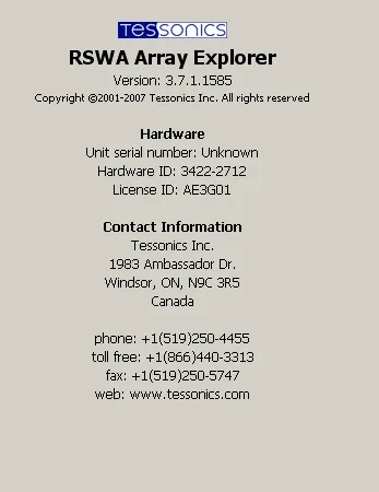
Inspection and Information Area
When you are not in an Inspection this area provides some information about the RSWA and contact information for Tessonics.
 {height=45%}
When you are in one of the inspection modes this area provides additional options (see Inspections).
Inspections
An Inspection is a group of measurements (for example, all the welds inspected on one body part). Inspections allow the RSWA to organize and sort measurements for storage and future review, and eliminates the hassle of users saving measurements on their own. The Inspection area is only shown if you are currently in an Inspection.
There are two types of Inspections available to choose from: custom inspection and part inspection.
Custom Inspection Mode
The custom inspection type allows you to measure welds and assign names to these welds as you check them. A screenshot of a custom inspection can be seen in Figure 18.
 {min-width=50%}
- Weld name
- Shows the welds name. The default names are numbered welds starting from one. Welds can be renamed individually by holding your finger on the weld until the pop-up menu appears (approximately 2 seconds) and then selecting Rename. There is also an advanced Auto-Generator feature, see Weld Name Auto-Generator for more information.
- Measurement thumbnails
- Each of these thumbnails represents a welds measurement. Clicking on a thumbnail brings the measurement back into the C-Scan for review, along with the history of measurements taken for that weld. This history list can be used to choose which measurement appears in the thumbnail; only the chosen measurement will be saved. There are two thumbnails because 3T stacks are supposed to be measured from both sides, and these measurements should be paired together.
- Decisions
- Each weld can have an associated pass or fail. Shown is either a check mark for pass, a cross for fail, or a dotted circle meaning no decision yet.
- Reasons
- Shows the reason chosen for failing a weld. Can also show the reason for passing a weld without measurement. During an inspection, the Pass, Fail, and Next Unit buttons appear enabled in the middle of the button bar.
The list of reasons for passing or failing a weld are programmed into the RSWA and cannot be changed by users. To change a welds pass or fail reason, simply hold your finger on the weld until a pop-up menu appears (for approximately 2 seconds) and select Clear Decision. You can now re-pass or re-fail the weld and select your new decision.
Starting New Custom Inspection
Custom Inspection can be started by clicking the New Inspection button in the top left corner of the screen. On the screen that pops up, choose Custom and press Next. You will be prompted to enter a name for the inspection. Entering a name is optional but doing so will make it easier to retrieve your inspection in the future. Now the New Inspection button changes to the End Inspection button.
Note
If no parts have been defined yet, pressing New Inspection automatically chooses Custom and prompts for a name of the inspection.Ending and Saving Custom Inspection
Clicking the End Inspection button or trying to close Array Explorer will ask you if you would like to save the inspection. If you choose to save the inspection, Array Explorer will do so without any further input from the user; i.e. you do not have to provide a filename or select a place to save the inspection.
Note
Once an Inspection is saved, welds with decisions cannot be modified.Renaming Welds
Push and hold a weld in the weld list. From the pop-up menu select Rename. Type in the new weld name, then push OK.
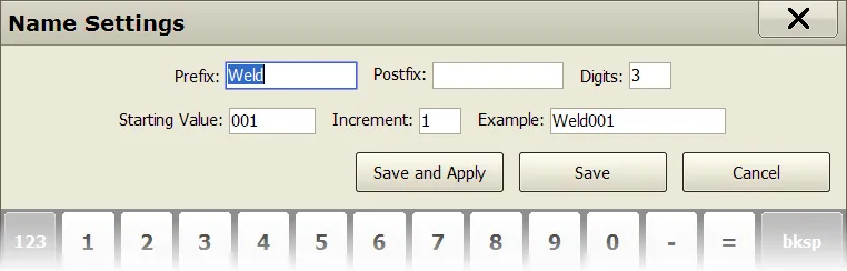
Weld Name Auto-Generator
If your weld names are similar, you can instruct the RSWA to name your welds for you using the weld name Auto-Generator.
 {width=60%}
Push and hold a weld in the weld list. Choose Name Settings from the pop-up menu. Doing so will launch the window shown in figure 19. This window allows you to customize the prefix, postfix, number of digits, starting value, and increment. It also provides and example of what the resulting name will look like. To save the changes the user must click either the Save or Save and Apply button. Clicking save will apply the changes to all future welds; clicking Save and Apply will apply the changes to all existing and future welds.
Part Inspection Mode
The part inspection type is an advanced inspection type that uses coordinator defined factory information. All of the factory information is stored in a desktop PC and distributed to the RSWA. RSWA units then use this information to guide and organize an inspection, letting the inspector focus on inspecting welds. All of the factory data is created using the Template Designer application, and then imported into an RSWA via the RSWA Synchronizer program.
A screenshot of the information area in part inspection mode can be seen in figure 20.
 {height=45%}
Similar to a custom inspection, you can check welds and pass or fail them as you go along. Unlike a custom inspection, you follow a predetermined list of welds that an administrator has created for you. They are already named and ordered, and all that needs to be done is to inspect the welds.
List of Images
A part can have one or more images that show the part in different views. Front side, back side, etc. This list shows all the images that belong to the part being inspected. You can choose which image is shown by clicking on the image thumbnail.
Image Area
Shows the current image and the welds that are on it. The currently selected weld that is being measured is shown highlighted to help an Inspector find the weld to be measured. The buttons in the image area are explained in the following table:
| Button | Description |
|---|---|
 | Zoom in and out the image, centered on the currently selected weld |
 | Toggle between showing all the welds or only the currently selected weld |
 | Toggle between a regular size and full screen image display |
Weld List
This part shows the list of welds that are to be measured for this part. An operator can check the welds in any order they like by selecting the weld they want to check from the list.
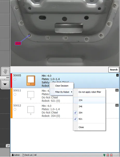
If the part has robot information, the list can be filtered to only show welds from specific robots by clicking and holding down on the weld list. See figure 21.
 {height=50%}
Just like in a Custom Inspection, a Part Inspection allows using Pass/Fail buttons to pass or fail the current weld. Instead of a New Weld button however, a Next Unit button is provided. This lets you move to the next Inspection Order or repeat the same Inspection Order.
Starting New Part Inspection
In the main Array Explorer window, click the New Inspectionbutton button. In the window that pops up select Part and press Next. A list of parts that have been programmed into the RSWA is shown. Choose the part that you want and press Nxt. The next window asks you to name your Inspection, enter the part name (or leave it blank) and press Next. If there are any Inspection Orders defined for this part, a final window pops up showing a list of Inspection Orders to choose from. Select one and press Finish. The window closes and you can start checking welds.
Note
If no Inspection Orders have been defined, the RSWA simply shows all welds on the selected part in alphabetical order.Ending and Saving Part Inspection
Pressing the End Inspection button anytime during a Part Inspection will save your Inspection to the RSWA.
Opening Inspections
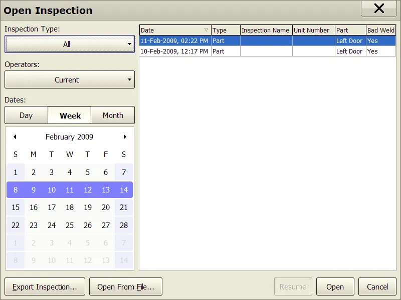
To open a saved inspection, click the Open Inspection button. This will launch the Open Inspection window shown in figure 22.
 {min-width=45%}
This window helps you find the desired inspection by providing filters and sorting options.
- Inspection Types
- Choose an inspection type to display, or select All to show all Inspection types.
- Operator
- Choose an operator’s name to show inspections performed by the selected operator, or select All to show inspections from all operators.
- Date Range
- Choose either day, week or month. You will see the selection in the calendar change to reflect the chosen option.
- Calendar
- Click to select which dates are shown in the Inspection List.
The table on the right shows all the inspections that meet the above criteria. The table headers can be used to sort the table based on a given attribute.
When you locate the inspection, select it in the table, then click Open or Resume.
- Open
- Click the Open button to open the selected inspection in read-only mode for review.
- Resume
- Click the Resume button to open the selected inspection in resume inspection mode.
Note
Previously measured welds cannot be modified in a resumed Inspection.Upon saving, a resumed Inspection will update it’s date and time to the new save time. This may mean that the inspection moves from an older date to a newer one. Also, a resumed inspection needs to be synchronized again with the Coordinator’s PC if you want to see the newer data in the RSWA Reporter software.
By default, all inspections are stored in a database. This allows for fast storage, retrieval, and sorting of the measurements. Access to individual inspection files may be needed however, and the two following options allow exporting and importing inspections as files:
- Export Inspection
- Clicking this option allows you to save a copy of a single inspection into a file.
- Open from File
- Clicking this option allows you to load an inspection from a file into the RSWA for review.