Template Designer
Tessonics Corporation has made every effort to ensure the accuracy and completeness of this document; however, because ongoing efforts are made to continually improve the capabilities of our products, we cannot guarantee the accuracy of the contents of this document. We disclaim liability for errors, omissions, or future changes herein.
Tessonics Corporation and its subsidiaries reserve the right to make changes, corrections, enhancements, modifications and improvements to its products and/or to this document at any time without notice.
Information in this document supersedes and replaces information previously supplied in any prior versions of this document.
Tessonics and the Tessonics logo are trademarks of Tessonics Corporation.
All other trademarks mentioned herein are the property of their respective owners.
©2007–2024 Tessonics Corporation. All rights reserved.
No part of this document may be copied, reproduced, or translated, without the prior written consent of Tessonics Corporation.
Note
This section describes an older version of the Template Designer. Tessonics recommends using newer version of the designer software for managing RSWA data.The Template Designer Application is used for storing factory information into a database for RSWA operation. This enables your RSWA to use more advanced inspection types that help guide an inspector, keep track of all measurement data, and enable advanced data reporting for administrators.
Here are some terms that are used frequently throughout this section:
- Part
- A single real-life object that is manufactured with spot-welds.
- Part Group
- A collection of parts.
- Default Group
- The “Default” part group that always exists and cannot be modified by the user. If it is the only group that exists, the group selector is not shown on an RSWA unit. If it is empty, it is hidden from view and not used.
- Image
- A small picture showing a part and the welds that are on it. Each part can have many images (see Image Editor).
- Weld
- A spot-weld on a part. Each weld contains a number of properties for that spot-weld (see Weld List).
- Weld Marker
- The small label and circle on an image that indicates where a particular weld is on a part or model.
- Reason
- A short explanation as to why a weld was passed or failed (see Reason Manager).
- Inspection Order
- A numbered list of welds that defines the welds and order in which they are inspected (see Inspection Order Manager).
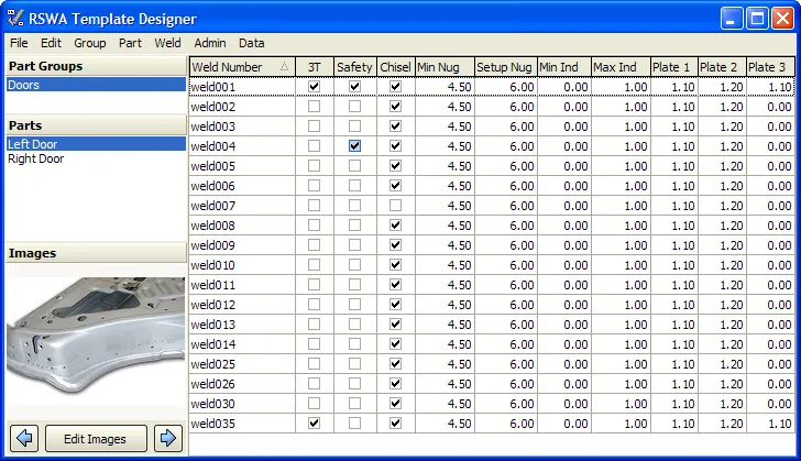
Main Window
 {min-width=50%}
Part Groups
Shows a list of all the part groups that have been defined. Each part group can contain a number of parts. This is to break down and help organize a long list of parts that otherwise might be difficult to work with.
Parts Area
Shows a list of all the parts that belong to the currently selected part group. Selecting a part will make it become the active part. This will show its corresponding welds in the weld list and one of its images in the Image Area.
Images
This area shows an image of a spot welded part. You can change which image is shown by clicking on the arrow buttons on the bottom. The images available to be shown correspond to which part you have selected. To manage the images press the “Edit Images” button on the bottom (see Image Editor for more details.)
Weld List
The list of all the welds that belong to a selected Part. Using this grid you can add, edit, and modify welds in the list. This list looks and acts much like a regular spreadsheet does. Each row represents one spot weld on an assembly line. Each column represents a property of a weld, and are explained below.
- 3T
- A checkmark indicates if this weld is a 3T weld or not.
- Safety
- A checkmark indicates whether or not this weld is a safety weld.
- Chisel
- A checkmark indicates whether or not this weld can be checked by a hammer and chisel
- Min Nug
- The minimum size of the nugget
- Setup Nug
- The setup (nominal) size of the nugget
- Min Ind
- The minimum size of the indentation
- Max Ind
- The maximum size of the indentation
- Plate1
- The thickness, in mm, of plate 1
- Plate2
- The thickness, in mm, of plate 2
- Plate3
- The thickness, in mm, of plate 3. This is only used if the weld is marked as 3T.
Like a spreadsheet, use the arrow keys to move around the cells and enter in new values. Pressing down to the end of the list will add a blank new weld. Pressing Insert will also add a new weld to the bottom of the list. Pressing Escape during any editing or adding will cancel the action.
The grid can be sorted by any one of these columns by clicking on the column name at the top of the grid. If you are adding or editing a weld, sorting will cancel the action.
To delete a weld, highlight the weld you want and press Delete. Be sure that you are not editing the weld before you press delete.
Main Menu
The main menu provides the following commands:
- File→Save
- Save all changes made to the database. Any current weld editing is cancelled during a save.
- File→Exit
- Exit the Designer application.
- Edit→Paste from Clipboard
- See Import Weld Data for more information.
- Edit→Import XML File
- Use this function to select a properly formatted XML file for input into the designer. See XML Import for more information.
- Group→Add Group
- Creates a new, empty part group.
- Group→Delete Group
- Deletes the currently selected group. All parts that belonged to this group are moved to the Default group.
- Group→Rename Group
- Allows you to rename a part group.
- Part→Add Part
- When selected, a small box pops up asking for the name of the new part. Type in a part name, and then press OK. The new part then is added and selected in the Part List.
- Part→Rename Part
- Allows you to rename the currently selected part.
- Part→Delete Part
- Deletes a part, and all of the associated welds, images, and inspection orders. This option is only available to the admin user, due to deletion being unrecoverable.
- Part→Move Part
- When selected, a list of other part groups becomes available. Select a different part group, and the currently selected part is moved to that part group.
- Weld→Add Weld
- Add a new weld into the weld list. This is the same as pressing the Insert key on your keyboard.
- Weld→Delete Welds
- Deletes the currently selected welds from the list. This is the same as pressing the Delete key on your keyboard.
- Weld→Edit Selected
- Allows editing many welds at once. This option is useful for setting many different welds to same parameters without entering information repeatedly.
- Admin→Reasons
- Launches the Reason Manager, see Reason Manager.
- Admin→Inspection Order
- Launches the Inspection Order Manager, see Inspection Order Manager.
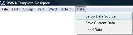
- Data→Setup Data Source (Admin user only)
- Launches the Data Source wizard, see Data Source Wizard.
- Data→Save Current Data (Admin user only)
- Allows saving all current RSWA data (users, passwords, inspections, etc) into one file for backup purposes.
- Data→Load Data (Admin user only)
- Lets you choose an RSWA data backup file to restore to.
Caution
Load Data will completely overwrite all of your current data. Use with caution!Note
All data operations can take a long time to complete, have patience.Import Weld Data
Weld data can be imported from other applications, like Excel, by using the ‘Paste from Clipboard (Ctrl + P)’ feature found in the Edit menu. This feature will add any weld data found on the clipboard to the selected part. If the clipboard contains duplicate weld data or data that is not formatted correctly it will simply be ignored.
Import Weld Data from Excel
If you already have all your weld data in Excel, rearrange it so it looks like the data in the example. If you are missing certain information, just use a default value, like 0 or ’n’. Any default values can be edited later on from within the designer. Once your data is formatted correctly, select it all, copy it to the clipboard (Ctrl+c), bring up the designer, and then ‘Paste from Clipboard (Ctrl + P)’.
| Weld Number | 3T | Safety | Chisel | Min Nug | Setup Nug | Min Ind | Max Ind | Plate 1 | Plate 2 | Plate 3 |
|---|---|---|---|---|---|---|---|---|---|---|
| weld123 | n | y | y | 4.5 | 5.5 | 0.05 | 0.5 | 1.1 | 1.2 | 0 |
| weld456 | y | y | y | 4.5 | 5.5 | 0 | 0 | 1 | 1.5 | 1 |
| weld789 | n | n | n | 0 | 0 | 0 | 0 | 0 | 0 | 0 |
Import Weld Data from other applications
When data is copied in Excel, columns are separated by tab characters and rows are separated by new line characters. So when copied from Excel, the example above will actually store the following string to the clipboard. Any software that can produce weld data in this format can export weld data to the designer.
weld123[tab]n[tab]...[tab]0[new line]weld456[tab]...
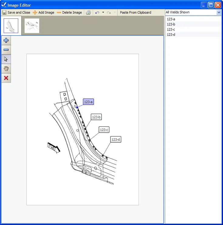
Image Editor
The Image Editor is used to manage and edit the images associated with the currently selected Part. Using this editor allows you to add images to a part and place weld markers on each image. A screen shot of the Image Editor is shown below:
 {min-width=40%}
Toolbar
- Save and Close
- Save all changes made and exits the Image Editor. (This only saves changes made inside the Image Editor. You still need to select “Save” from the main menu in order to save all changes to disk).
- Add Image
- Clicking this brings up the usual “Open File” pop-up most windows users are familiar with. Simply choose the image that you want to add and press OK.
- Delete Image
- Clicking this deletes the currently selected image. (It is only truly gone if you save and close the Image Editor and then save from the Designer main menu).
- Click this button to print out the Image and the weld markers that are placed on it.
- Weld List Filter
- Clicking and selecting an option from this filter will only show welds that meet the filters conditions. This is meant to trim down the possibly long list of welds, and to help point out welds that might be missing or missing a marker on an image.
- Undo
- Undo the last change you made.
- Redo
- Redo the last change (revert the pervious Undo operation).
Image Selector
This horizontal bar shows all of the images associated with the currently selected Part, and shows which image is currently being shown. If the number of images to choose from is large, two buttons appear that let you scroll horizontally through the list of images to find the one you are looking for.
Weld List
Shows a list of welds that can be placed on an image. Clicking on a weld that is already assigned to the currently displayed image will highlight that weld on the image. To add a weld to an image, just drag and drop the desired weld onto the image. A weld cannot appear in the same image twice; trying to add a second marker for a weld for the same image results in the first marker being erased.
Image Display
This large section shows what will be displayed on the RSWA screen. It shows the currently selected image and all of the markers that are placed on this image.
The buttons in the upper left corner of the image display provide the following functions (image on the right of the screen):
 {options=right height=7em}
- Zoom in
- Zoom out
- Switch to Selection mode
- Switch to Pan mode
- Delete selected markers
To move a marker and its tag, simply click on the marker or tag and drag it around the image. Clicking on a marker will also highlight the markers weld in the weld list automatically
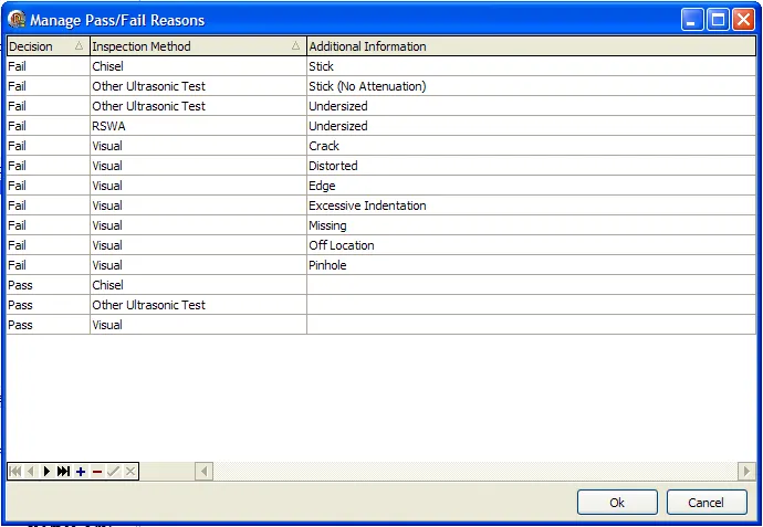
Reason Manager
The reason manager lets you add, delete and modify the reasons an RSWA user can select for passing or failing a weld.
 {min-width=50%}
Each reason consists of the following properties:
- Decision
- Either pass or fail
- Method
- How it was determined that this weld passed or failed
- Description
- Optional additional information
Similar to the weld list, the reason manager shows a table of reasons. Each row represents one reason, and each column is a property of that reason. You can add and delete reason using the buttons in the lower left corner of the list.
To edit a reason, just click on the appropriate cell and enter in the new value. Press OK to save you changes and return back to the main window, or press “Cancel” to lose your changes and return back to the main window. (Once again, all of your changes are only truly saved if you select “Save” from the main menu).
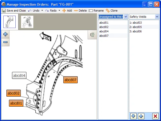
Inspection Order Manager
An inspection order specifies which welds are inspected and the order that they are inspected. The inspection order manager lets you add, delete, and modify the inspection orders for the currently selected part.
 {min-width=50%}
The idea behind inspection orders is to guide an RSWA user to only check certain welds, and to check them in a particular order. The avoids needless shuffling during spot-weld inspection and lets an inspector focus on the welds that are most important.
Note
If no inspection orders are defined for the current part (“Default” is empty), then all the welds will appear on an RSWA in alphabetical order.The inspection order manager was written to be simple and intuitive. To add welds to an inspection order, either drag and drop or double click on welds and drag them into the inspection order list. Moving and deleting involves either using the three buttons underneath the inspection order list or dragging and dropping. Read on for a more complete description of this manager.
Toolbar
- Save and Close
- Saves any changes you have made and exits the Inspection Order Manager. Keep in mind you still need to select “Save” from the main menu to finally write the changes to disk.
- Undo
- Will undo the last change you made. Pressing the arrow on this button will show the list of actions that you can undo.
- Redo
- The opposite of undo, allows you to revert the actions that you have “undone”. Pressing the arrow on this button will show the list of actions that you can redo.
- Add
- Lets you add a new inspection order to this part. A window will pop up asking for you to input the inspection order name (For example, “Critical Welds”).
- Delete
- Pressing this will delete the currently selected inspection order. A window box will pop up to double check you actions.
- Rename
- This allows you to rename the currently selected inspection order. A window will pop up asking you to input the new name.
- Clone
- This will clone (duplicate) the currently selected inspection order into a new inspection order with a different name. The reason for this action is so that you can take an existing inspection order and make a new, slightly different inspection order with less work.
Image Selector
Similar to the image editor, this horizontal list shows all of the images belonging to the currently selected part. If the list grows too large, some scrolling buttons will appear. Clicking on a thumbnail will show that image in the image area.
Image Display
The image display shows the currently selected image and weld markers that are on it. Which weld markers (if any) are shown depends on what weld filter is chosen in the weld List. Similar to the image editor, you can zoom in and select welds. You can always pan and select welds, so no hand or pointer button is provided. At the top right there is a button that will toggle on or off the displaying of all weld markers.
To add a single weld to the current inspection order, double click that weld. It will be added to the end of the inspection order.
You can also add welds to the current inspection order by dragging and dropping welds from the image display into the inspection order list. Select the welds that you would like to insert by clicking on them (hold down Ctrl to select multiple welds), and then drag them into the inspection order list. You will see an insertion bar appear to let you know where these welds will be inserted.
The image display is meant to help you visualize the inspection order as you work, and does not represent all welds that are on a part. This is due to the fact that not all welds might be shown in an image. Some welds might not be in any image, but are still on a part. For this reason, consider the image area to be a useful tool, but not the primary source for welds.
Weld List
This list shows the welds that are on a part. Just above this list is the weld list filter, which only shows welds that meet certain conditions. This filter acts on both the weld list and the current image. The options are as follows:
- All Welds
- This option filters nothing, simply showing all welds that belong to the current part.
- This Graphic Only
- All welds in the current image are shown. Only welds that are in the current image are shown in the weld list.
- Assigned to this Order
- Only welds that are part of the currently selected inspection order are shown. Use this option to visually see in the image area which welds are part of the current inspection order.
- Unassigned to this Order (default)
- Only welds that are not part of the current inspection order are shown. This way, as you add welds to the current inspection order, you see them disappear and you do not re-add them.
- Unassigned to any Order
- Only welds that are not part of any inspection order are shown. Use this option as a check to see if any welds have been left out.
To add a weld from the weld list to the current inspection order, just double click that weld. It will add to the end of the current inspection order.
As with the image display, you can also select some welds first and then drag and drop them to a specific position in the current inspection order. Hold down Ctrl key and make your selection of welds in the list, and then drag them over the inspection order list. An insert cursor will appear showing where the welds will be inserted, and let go of the mouse button to insert them.
Inspection Order List
This list shows the current inspection order. A numbered list of welds is shown, corresponding to the order in which those welds will be checked. It it sorted by position, the top is where the inspection order starts and the bottom is where it ends. Above the list is the inspection order selector. Click this will bring up a list of all the inspection orders for this part. Click the inspection order that you want, and that inspection order will be shown and become the current inspection order.
To select welds in the inspection order simply click on them. (Hold down Ctrl key to select multiple welds). You will see as you select welds, they are also selected in the image area and the weld list. This is to help visualize the inspection order.
Once you have selected some welds in the inspection order, you can perform the following actions:
- Move
- Pressing either the up or down arrow at the bottom of the inspection order list will move the selected welds up or down one spot in the list. You can also do this using drag and drop, similar to how welds can be added in the first place.
- Delete
- Pressing the X button at the bottom of the Inspection Order list will delete the selected welds from the inspection order. You can also press Delete on the keyboard to do this.
XML Import
XML Import provides a way to automatically import any data that can be hand created in the template designer.
XML Import option can import parts, part groups, images, welds, inspection orders, and weld markers, like a more advanced version of paste from clipboard. This feature is mainly meant for IT managers who already have their factory data in some electronic format, and want to quickly import it for RSWA usage.
For more information, please contact Tessonics.
Data Source Wizard
All of the data (parts, users, measurements, etc..) that is used by or collected from the RSWAs is stored on the desktop computer where the Synchronizer, Template Designer, etc… is installed. It is possible to tell the software to store and retrieve data from a different location like a shared network drive. Storing the data on a shared network drive has two major benefits:
- network drives are usually backed up on a regular basis
- data can be shared by all who need it
There are two reasons you would use the data source wizard:
- move existing data to a shared location (i.e. make it available to everyone)
- point software to a shared location that already has data
It is important to know which action you are going perform before using the wizard.
Opening the Data Source Wizard
Changing the data source is an important operation and care should be taken when switching data sources. Because it is an important procedure, you must be logged in as Admin in order to use it. When you log in as Admin, a new toolbar options will be available. To open the Data Source Wizard, select ‘Data > Setup Data Source’.
 {min-width=50%}
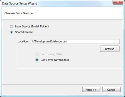
Moving existing data to a shared location
The goal here is to make the data stored on a desktop accessible to others by moving it to a shared location.
 {min-width=40%}
- make a new folder on the drive
- open the data source setup wizard
- select shared source and browse to the new folder
- you may get an error message indicating some file are missing; this is ok
- double check that the option ‘copy over current data’ is selected, then click next
- uncheck ‘Make Full Backup of current Data’, then click next
- data will not be deleted from your hard drive
- read the summary, then click finish
Once the data is copied over, the designer will restart. After it restarts, everything should look the same, however, now all changes will be saved to the new data source.
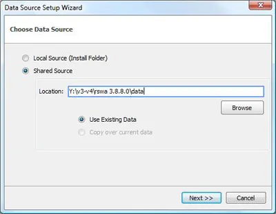
Pointing software to a shared location that already has data
The goal here is to tell the software to work with the data that is saved on the shared network drive.
 {min-width=40%}
- figure out where the data is saved
- open the data source setup wizard
- select shared source and browse to the new folder
- you should not get any error messages
- double check that the option ‘Use Existing Data’ is selected, then click Next
- uncheck ‘Make Full Backup of current Data’, then click Next
- data will not be deleted from your hard drive
- read the summary, then click Finish
The software will restart. After it restarts, you should have access to the data that is on the shared drive.
Image Optimization
One of the major factors that slows down the operation of RSWA is large images. If the imported graphic is too large, the data transfer during synchronization takes longer. The time it takes to load an image in the Array Explorer is also longer.
To address these issues, the image optimization dialog box allows to resize and recompress the images in the database.
Note
Please back up the database before optimizing imagesTo optimize the images log in as Admin, then in the main menu, choose Data -> Optimize Images.
 {min-width=40%}
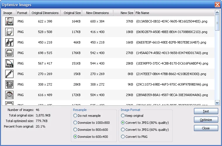
The upper part of the image optimization dialog shows all the images in the database.
Image List
- Image
- shows thumbnail of an image
- Format
- current storage format of an image, webp or JPEG
- Original Dimensions
- dimensions of an original image in pixels
- Original Size
- size of an original image file
- New Dimensions
- dimensions of an optimized image in pixels
- New Size
- size of an image file after the optimization
Statistical Data
Statistical information is shown in the lower left corner:
- Number of images
- the number of images in the database.
- Total original size
- the total size of images before optimization
- Total optimized size
- the total size of images after optimization
- Percent from original
- the percentage of optimized size to the original size
Resample Box
The Resample box allows to choose how an image is resized:
- Do not resample
- keep original dimensions of an image
- Downsize to 1000x800
- optimized image dimensions not to exceed 1000x800 pixels
- Downsize to 800x600 (recommended)
- optimized image dimensions not to exceed 800x600 pixels
- Downsize to 600x400
- optimized image dimensions not to exceed 600x400 pixels
Image Format
The Image Format allows to choose the new storage of an image:
- Keep original
- keep original storage format
- Convert to JPEG (80% quality)
- save as JPEG image with moderate compression
- Convert to JPEG (60% quality)
- save as JPEG image with high compression
- Convert to webp
- save as webp image
For most images, it is recommended to choose JPEG (80% quality).
Completing Image Optimization
After you set up all the parameters, push the Test button and verify the statistical information to see how much space the optimization will save.
Proceed to optimization by clicking the Optimize button.
Once optimization is completed, click the Close button.