Designer
Tessonics Corporation has made every effort to ensure the accuracy and completeness of this document; however, because ongoing efforts are made to continually improve the capabilities of our products, we cannot guarantee the accuracy of the contents of this document. We disclaim liability for errors, omissions, or future changes herein.
Tessonics Corporation and its subsidiaries reserve the right to make changes, corrections, enhancements, modifications and improvements to its products and/or to this document at any time without notice.
Information in this document supersedes and replaces information previously supplied in any prior versions of this document.
Tessonics and the Tessonics logo are trademarks of Tessonics Corporation.
All other trademarks mentioned herein are the property of their respective owners.
©2007–2024 Tessonics Corporation. All rights reserved.
No part of this document may be copied, reproduced, or translated, without the prior written consent of Tessonics Corporation.
The Designer application is used for storing factory information into a database for RSWA operation. This enables your RSWA to use part mode inspections to guide an inspector, keep track of all measurement data, and enable advanced data reporting.
First Run
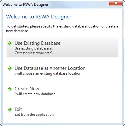
If the database location has not been yet initialized, the designer will show a dialog box that allows selecting the database location.
 {min-width=45%}
If you have used the older version of RSWA designer before, the first option allows to connect to the existing database.
Use the Create New option to create a new database on your local disk or on a network drive (see Creating New Database for more details).
The location of your database is stored in a user profile. If you have multiple users using the same computer, each of them will have to specify the location of the database.
Main Window
 {min-width=45%}
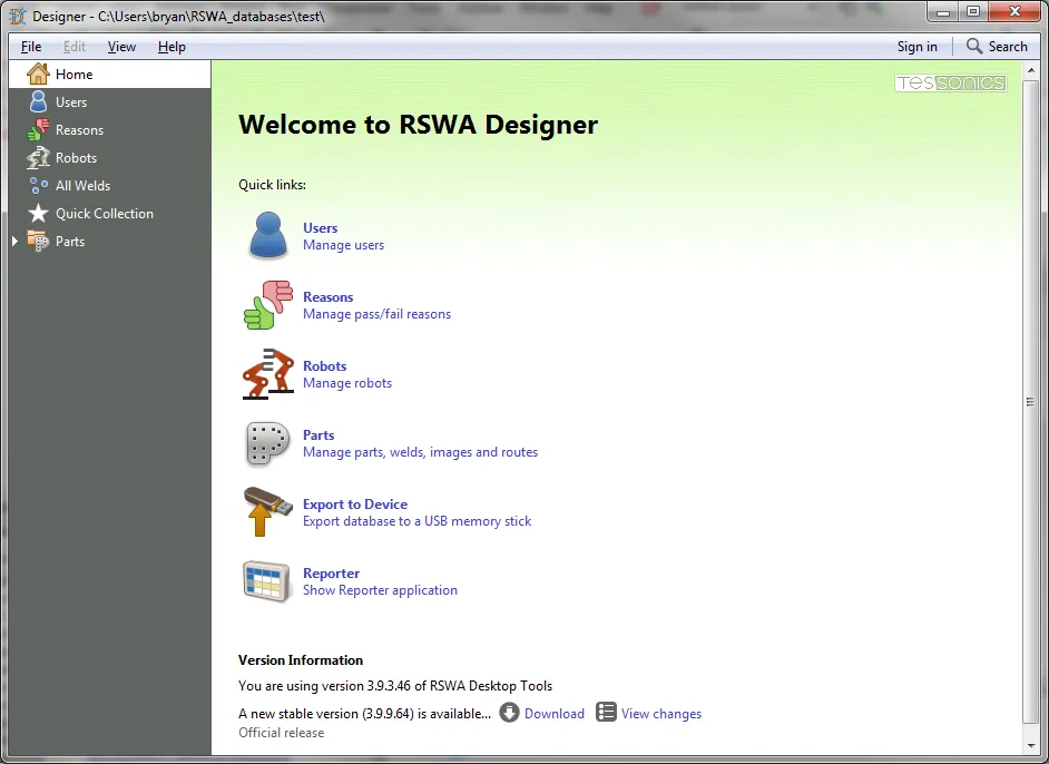
The main window of the RSWA Designer contains:
- Main menu at the top provides access to commands, options, signing in and search
- Navigation tree at the left allows switching between editing views
- Editing area covers the rest of the Designer’s window, it shows home screen and serves as the main view for various data management tasks
Using Home Screen
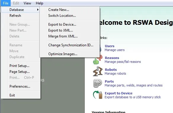
Home screen provides quick links to common management tasks for Parts, Robots, Users, and Reasons. There is also a link for exporting database to a memory stick for synchronization with RSWA device, as well as a link to open the reporter application.
At the bottom of the main screen, the application displays its current version. If the Internet connection is enabled, if will show the information on available software updates.
Signing In
In order to perform some operations you need to be signed in. Most of the viewing tasks can be performed right away when you start the designer, most of data editing tasks will require a user with sufficient permissions to be signed in. Some critical tasks, like user management, require Admin user to be signed in.
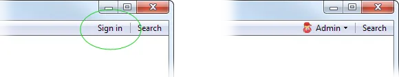
You can sign in by clicking the Sign In item in the main menu, then choose a user and, if necessary, enter password.
 {width=100%}
The Sign In item then changes to a user name to indicate successful sign in. You can click on this item again to sign out.
Managing Users
RSWA Designer provides centralized user management. The users that are created in the designer are automatically populated to RSWA units during the synchronization process.
All users have the option of password protecting their account but are not required to do so. Passwords are case-insensitive (i.e. PAssWOrd = password) and allow for any combination of characters (including spaces). In the event that a user forgets their password, it can be reset by the user management software.
Permissions are used to limit and control users access to restricted functionality and data. Users should be trained to use the restricted features and data before they are granted permission.
In addition to regular users, there is also an Admin user. This user has access to all applications, settings and data. This user is password protected and cannot be deleted or edited in any other way. This user is only meant to be used for administration purposes.
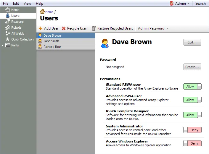
To manage users, select Users node in the navigation tree or click on Users link in the Home screen. The list of users is shown on the left hand size. When you select a user from the list, user settings are shown in the main view (Figure #).
 {min-width=45%}
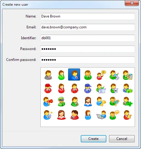
To add a new user, click the Add User button or choose Edit→Add User from the main menu. Then enter user name, email (optional), identifier (optional) and if you want to password protect the user account, enter user password twice (Figure #). Finally, choose a user picture and click the Create button.
 {min-width=45%}
Identifier is an optional string of characters that can be used to link RSWA users to other databases.
To grant or revoke permissions, click on a switch next to the permission description in the main view. You can also change other user properties, change or assign password by clicking on the corresponding buttons in the main view.
To recycle a user, click on the Recycle User button or choose Edit→Recycle User from the main menu. The user is then tagged as inactive and removed from the user list. The user data still stays in the database but it will not be visible in log-in screens.
To make a user active again, click the Restore Recycled Users button or choose Edit→Restore Recycled Users from the main menu. Then check the users you want restored and click the Restore button.
The Admin user is managed separately. You can only change its password. If you know the old user password, it can be changed by clicking Admin Password→Change, then enter the existing password and enter the new password twice, then click the Change button. If the existing admin password is lost, there is an option to reset the password by choosing Admin Password→Reset. You will need to contact Tessonics to obtain a special password reset code.
The user management page also contains options to control the behavior of the login dialog for the RSWA. Clicking on the Login Options menu button allows you to show or hide user icons and names. When user icons and names are not shown, the login dialog only displays fields for entering a user name and password.
Managing Decision Reasons
Decision reasons provide textual description of reasons for passing or failing welds in the Array Explorer software.
 {min-width=45%}
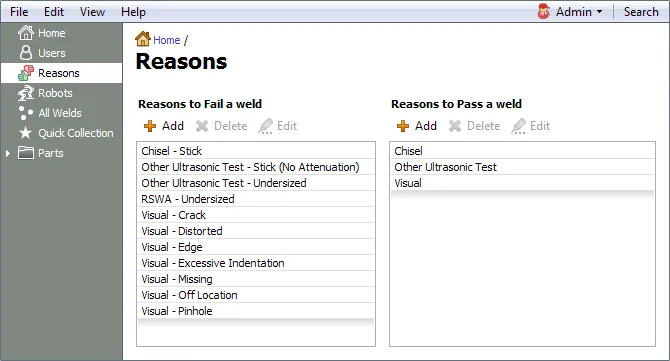
To modify the list of reasons, select the Reasons node from the navigation tree. In the main view, you are presented with two lists of reasons to fail and pass a weld. Click the Add button to add a new reason, then type in the testing method (e.g. RSWA) and the description of the decision (e.g. Undersized weld). It is allowed to have one of the fields empy. For example description for passing a weld is empty by default.
To delete a reason, select one or more reasons from the list, then click the Delete button. To select more than one reason for deletion, use Ctrl or Shift key on your keyboard.
To edit a reason, select the reason from the list, then click the Edit button, modify testing method and description properties, then click Update.
Reasons in the Array Explorer software will appear in the same order as they are shown in the Designer’s reason view. You can reorder reasons in the list by dragging items with the mouse.
Managing Robots
Robot descriptions allow to assign welds to certain robots. Robots are organized into robot groups. For example, one can create a robot group that will contain all robots in a cell. Managing robots is optional, it does not influence the operation of software.
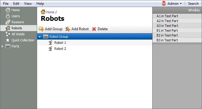
To manage robots, select the Robots node in the navigation tree. The main view contains the list of robots organized by a robot group. On the right hand side, a list of welds is shown. When a robot or a robot group is selected in the main view, this list shows all the welds that belong to this robot (or a robot group).
 {min-width=45%}
To create a new robot group, click the Add Group button, then type in the group name. To create a robot inside a group, select a group to which a robot will belong, then click the Add Robot button.
To delete a robot or a robot group, select it, then click the Delete button. Please note that when you delete a robot or a robot group, all the welds that link to it will no longer be associated with any robot.
Links between robots to welds are managed in the weld view when editing parts. You can also break the connection between a robot and a weld from the robots view by right clicking on a weld in the list on the right hand side and choosing Remove Weld option from the popup menu.
Managing Parts and Part Groups
Parts contain weld information, graphical images and inspection routes. Parts are organized in part groups.
To see all part groups, click on the Parts node in the navigation tree. To see parts within a part group, click on a group in the navigation tree.
To create a new part group, select the Parts node in the navigation tree, then select in main menu File→New Group. Choose the name for the part group and click Create.
To rename a part group, select the group in the navigation tree then chose File→Rename Group from the main menu. Enter the new name and click Rename.
To delete a part group, select the group in the navigation tree, then choose File→Delete Group from the main menu. Please keep in mind that all the parts contained within the group will also be deleted.
To create a new part, select a group that will contain it in the navigation tree, then choose File→New Part from the main menu. Enter the new part name then click Create.
To rename a part, select the part in the navigation tree, then choose File→Rename Part from the main menu. Enter the new name and click Rename.
To delete a part, select the part in the navigation tree, then choose File→Delete Part from the main menu. Please keep in mind, that the information for all welds, images and routes associated with the part will also be deleted.
Each part contains a list of welds, images and routes.
Using Quick Collection
Weld entries can be tagged with a star symbol to put them into a quick collection. The quick collection is a convenient way of temporarily tagging certain welds and performing additional operations on them.
In weld view, image view, route view and in other location where welds are displayed, there is usually an option of adding or removing a weld to a quick collection.
To see all the welds that are assigned to a quick collection, choose the Quick Collection node in the main navigation tree.
Please notice, that the quick collection membership is only persistent within the current editing session, once the designer is restarted, the quick collection will be emptied.
Managing Weld Information
To switch main view to weld information display, select a part in the navigation tree then in the main area, click on Welds, or expand a part node in navigation tree, then click Welds node.
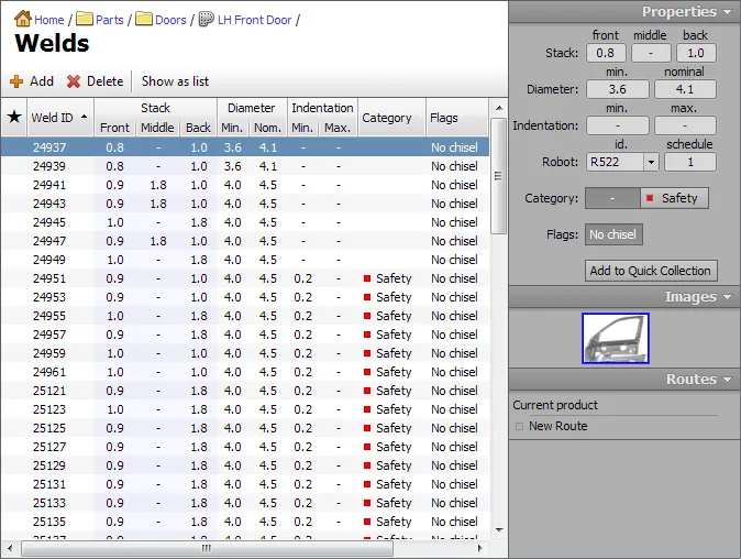
It is also possible to see a list of all the welds defined in the database by choosing All Welds The weld information display contains a grid of welds and a property panel on the right hand side.
The main grid shows weld properties in a spread sheet like view.
 {min-width=45%}
New welds can be inserted into the grid by clicking the Add button on a toolbar or by choosing Edit→Add Weld from the main menu. To remove welds, select one or more lines in the weld grid and click the Delete button or choose Edit→Delete from the main menu.
You can modify weld properties directly by clicking and typing a grid cell. Visible columns can be customized from main menu by clicking on View→Columns. The data in the grid can be sorted by clicking on the column header, or choosing View→Sort By from the main menu. It is also possible to group the displayed welds by stack, diameter, category or robot.
More than one weld can be chosen for group operations by holding Ctrl key while clicking on additional welds, or by holding Shift key to select ranges of welds.
The property panel on the right hand side shows a summary of weld properties for the currently selected weld. If more than one weld is selected, it will show properties that are common for all the selected welds. By editing the data in the property panel while multiple welds are selected, one can assign the same property to all the selected welds.
The very first column in the weld grid shows indicates whether the weld belongs to a quick collection. Welds can be added to or removed from the quick collection by clicking on the grid inside this column or by toggling Add to Quick Collection/Remove from Quick Collection button in the property panel.
Printing
The content of the grid can be printed by choosing the Print option from the main menu. The printed report will show the same welds and data columns as the grid on the screen.
Automated Tasks
It is possible to perform certain automated tasks on selected weld entries. To get started with automated tasks, choose one or more welds, then select Edit→Apply Formula from main menu.
In the current version of software the following automated tasks are available:
Calculate nugget diameter - allows to set values for minimal and nominal diameters automatically from plate thicknesses using common formulas such as 4√GMT and 3.5√GMT.
Flip weld - allows swapping of front and back plate thicknesses for selected welds.
Importing Data
To import existing weld information stored in a spreadsheet: copy cells from a spreadsheet into a clipboard, then choose Edit→Import from Clipboard from main menu.
 {min-width=45%}
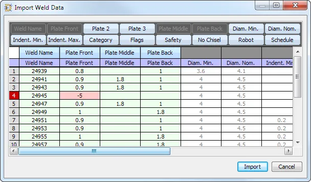
The Import Weld Data window consists of the following parts:
- The dark grey bar at the is a Descriptor Repository that contains available descriptors for different columns
- The Column Descriptors row contains descriptors assigned to various columns of imported data
- The Header Row contains column header cells from imported data
- The rest of the numbered rows are the imported data cells
Use the mouse to drag the column descriptors from the Descriptor Repository onto the Column Descriptors row to specify column types. For example, in the image above, the first four columns are attributed to Weld Name, Plate Front, Plate Middle, and Plate Back. The rest of the columns are not assigned and their content will not be imported. The layout of columns is saved between the sessions. Next time you perform the import it will try to use the previous column layout.
As a bare minimum, you have to specify which column contains the Weld Name value. Existing welds with matching names will be updated with new values, otherwise new welds will be created. If your imported data contains plate thicknesses for 2T welds in first two columns leaving the third column empty, use Plate Front, Plate 2 and Plate 3 descriptors. If your 2T plate thicknesses are stored in first and third column, leaving the middle column empty, use Plate Front, Plate Middle and Plate Back descriptors.
If the imported data already contains a header row, the software will try to automatically recognize it and automatically exclude this row from import. Otherwise, you can drag the header splitter with the mouse to specify which rows contain header information, the rest of the rows will be imported.
All the data is validated before actual import is performed. In the example above, row number 4 contains invalid value for the front plate thickness. The row number is highlighted with red and the cell which did not pass validation is highlighted with pink color. The rows that did not pass validation will not be imported.
Managing Part Images
Each part can be associated with images and hot spots for welds. Using part images is not required, but it provides a convenient guidance for the operator.
To switch main view to an image display, select a part in the navigation tree, then in the main area, click Welds, or expand a part node in navigation tree, then select the Images node.
 {min-width=45%}
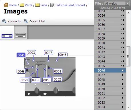
At the top of the view, below the toolbar there is a list of all images associated with the part. On the right hand side, there is a list of welds with filters. The rest of the area shows an image with hot spots.
To add a new image, click Edit→Add Image in the main menu, or right click in the image list area and choose Add Image from the popup menu. In the Add Image dialog, choose whether the new image will be opened from a file or will be based on one of the images that are already in the database, then click Next. If the file option was chosen, choose the file to use then click Open.
The next page in the Prepare Image dialog allows to crop the image, flip it and rotate it. When done, click Next.
The last page in the Prepare Image dialog allows to adjust resolution and compression format for the image. Adjust the necessary parameters, then click Ok to complete image import.
After the new image is imported you can drag and drop welds from the list on the right onto the image. The same weld can appear on more than one image. For convenience, the list of the right can be filtered to show all welds, welds that belong to current image, welds that do not belong to current image and welds that do not belong to any image.
When the part contains only one image, each entry in the weld list has a small icon on the right to indicate whether the weld is already inserted somewhere in the image (solid square) or not (small hollow square). If the part contains more than one image, there is an additional icon that indicates whether the weld belongs to any other image in this part.
To adjust hot spot placement, you can click and drag its target point or the label. To select more than one hot spot, hold Ctrl key on the keyboard and then click on hot spots. Alternatively, hold Ctrl key down, then click outside the hot spot and drag the selection rectangle. Selections in the image and in the weld list are automatically synchronized.
The image view will automatically try to arrange labels to minimize overlapping between them. If the labels still overlap due to high density, you can zoom image in and out. To control image zoom, use View from the main menu, image popup menu or a mouse wheel.
To remove a hot spot from the image, select it, then hit Delete key on your keyboard or choose Edit→Remove Hot Spot (or Edit→Remove Selected Spots for multiple selection) from the main menu or from the image popup menu.
Welds that belong to quick collection will have the star symbol next to them. You can use the popup menu or Edit option in the main menu to manage quick collection membership for selected welds.
It is also possible to jump to the weld view to see or modify specific weld properties. Select welds that you want to manage, then click Edit→Edit Weld details from main menu or from popup menu to switch back to weld properties view. The welds that you had selected in the image view will be automatically selected in the weld properties view.
Managing Inspection Routes
Once weld properties (and optionally images with hot spots) are defined, you can proceed with defining inspection routes. An inspection order specifies which welds are inspected and the order that they are inspected. Each part may contain multiple inspection routes. For example, critical safety welds may be organized in a separate route which then inspected more often when the rest of the welds.
Note: in the original version of the Template Designer, inspection routes were called inspection orders.
To switch main view to the route display, select a part in the navigation tree, then in the main area, click Routes, or expand a part node in navigation tree, then select the Routes node.
 {min-width=45%}
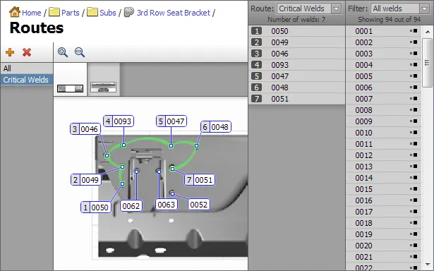
The list of currently assigned routes is shown on the left. New routes can be created by clicking the Add Route button or choosing Edit→Add Route from the main menu. Existing routes can be removed by clicking the Delete Route button or choosing Edit→Remove Route from the main menu. If you are creating a route that is similar to an existing route, you can click Edit→Duplicate Route to create a copy of an existing route, then make necessary modifications to it.
The area in the middle shows the graphical representation of the selected route.
There are two weld lists on the right hand side. The right-most list shows the sequence of welds that defines the currently selected route. The list on the left shows welds that belong to the part and a weld filter box.
Welds can be added to the end of the route sequence by double-clicking in the image or in the part weld list. It is also possible to drag the welds from the part weld list into the route list.
To remove entries from the route, select the corresponding welds, then choose Edit→Remove from Route from the main menu, or use the context menu.
Creating New Database
A new database can be created on a local disk, on a network folder or on a mapped network drive. Create an empty folder and make sure you have read and write access permissions to it. Then choose File→Database→Create New from main menu.
 {min-width=40%}
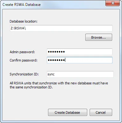
In the Create RSWA Database window, click the Browse… button next to the Database location field and choose the location where the new database will be created. Type in a password for Admin account, then type it again to confirm. Type in synchronization ID. All RSWA units that synchronize with the new database must have the same synchronization ID.
Click the Create Database button to complete this step.
Exporting Templates for RSWA Units
 {min-width=45%}
To transfer all information to RSWA you will need a memory stick.
Choose File→Database→Export to Device from the main menu or use the Export to Device short cut from the Home screen. Plug in the USB memory stick into the available USB port on your computer, then click the Export button. When transfer of templates is completed, click the Eject button, unplug the memory stick. Plug the memory stick into RSWA unit and use the Synchronizer to complete the data transfer.
Both the RSWA and the Designer must have the same Synchronization Id or they will not communicate. Choose File→Database→Change Synchronization Id… to set your Synchronization Id (see Synchronizer).
!Note: If your data transfer takes too long, consider optimizing images (see the Optimizing Images section).
Exporting and Merging Templates via XML Files
You can save the entire database (with users, parts, images, etc.) into a single XML file. To do so, choose File→Database→Export to XML from the main menu. Specify the location and the name of the XML file, then click the Save button.
This XML file then can be used, for example, to transfer parts from one database to another. Choose File→Database→Merge from XML from main menu, then choose an XML file that contains a database, then click Open to start the merging operation.
 {min-width=45%}
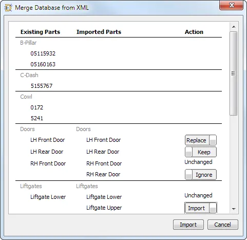
In the Merge Database from XML window the data is organized into three columns.
The first column shows parts and groups in the existing database. The second column shows parts and groups contained in the XML file. The third column allows to choose which parts to import.
The choice of actions is based on comparison between the existing parts and the new parts being imported.
- If there is a part in the existing database and there is no matching part in the XML file—no action is available
- If there is a new part in the XML for which no matching part is found in the existing database—choose between Import or Ignore
- If matching part found, but part data is the same in the exiting database and XML file—the action column shows Unchanged
- If matching part found and there are some differences in part data—choose between Replace and Keep
Optimizing Images
One of the major factors that slows down the operation of RSWA is large images. If the imported graphic is too large, the data transfer during synchronization takes longer. The time it takes to load an image in the Array Explorer is also increased.
To address these issues, the image optimization dialog box allows to resize and recompress the images in the database.
To optimize the images log in as Admin, then in the main menu, choose File→Database→Optimize Images.
 {min-width=45%}
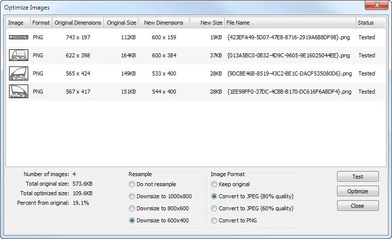
The upper part of the image optimization dialog shows all the images in the database.
Image List
- Image
- shows thumbnail of an image
- Format
- current storage format of an image, webp or JPEG
- Original Dimensions
- dimensions of an original image in pixels
- Original Size
- size of an original image file
- New Dimensions
- dimensions of an optimized image in pixels
- New Size
- size of an image file after the optimization
Statistical Data
Statistical information is shown in the lower left corner:
- Number of images
- the number of images in the database.
- Total original size
- the total size of images before optimization
- Total optimized size
- the total size of images after optimization
- Percent from original
- the percentage of optimized size to the original size
Resample Box
The Resample box allows to choose how an image is resized:
- Do not resample
- keep original dimensions of an image
- Downsize to 1000x800
- optimized image dimensions not to exceed 1000x800 pixels
- Downsize to 800x600 (recommended)
- optimized image dimensions not to exceed 800x600 pixels
- Downsize to 600x400
- optimized image dimensions not to exceed 600x400 pixels
Image Format
The Image Format allows to choose the new storage of an image:
- Keep original
- keep original storage format
- Convert to JPEG (80% quality)
- save as JPEG image with moderate compression
- Convert to JPEG (60% quality)
- save as JPEG image with high compression
- Convert to webp
- save as webp image
For most images, it is recommended to choose JPEG (80% quality).
Completing Image Optimization
After you set up all the parameters, push the Test button and verify the statistical information to see how much space the optimization will save.
Proceed to optimization by clicking the Optimize button.
Once optimization is completed, click the Close button.